What is a Topology?
The physical topology of a network refers to the configuration of cables, computers, and other peripherals. Physical topology should not be confused with logical topology which is the method used to pass information between workstations. Logical topology was discussed in the Protocol chapter.
Main Types of Physical Topologies
The following sections discuss the physical topologies used in networks and other related topics.
Linear Bus
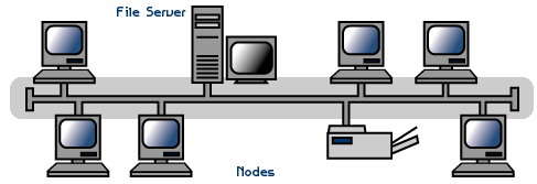
A linear bus topology consists of a main run of cable with a terminator at each end (See fig. 1). All nodes (file server, workstations, and peripherals) are connected to the linear cable.

Fig. 1. Linear Bus topology
Advantages of a Linear Bus Topology
- Easy to connect a computer or peripheral to a linear bus.
- Requires less cable length than a star topology.
Disadvantages of a Linear Bus Topology
- Entire network shuts down if there is a break in the main cable.
- Terminators are required at both ends of the backbone cable.
- Difficult to identify the problem if the entire network shuts down.
- Not meant to be used as a stand-alone solution in a large building.
Star
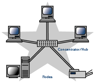
A star topology is designed with each node (file server, workstations, and peripherals) connected directly to a central network hub, switch, or concentrator (See fig. 2).
Data on a star network passes through the hub, switch, or concentrator before continuing to its destination. The hub, switch, or concentrator manages and controls all functions of the network. It also acts as a repeater for the data flow. This configuration is common with twisted pair cable; however, it can also be used with coaxial cable or fiber optic cable.

Fig. 2. Star topology
Advantages of a Star Topology
- Easy to install and wire.
- No disruptions to the network when connecting or removing devices.
- Easy to detect faults and to remove parts.
Disadvantages of a Star Topology
- Requires more cable length than a linear topology.
- If the hub, switch, or concentrator fails, nodes attached are disabled.
- More expensive than linear bus topologies because of the cost of the hubs, etc.
Tree or Expanded Star
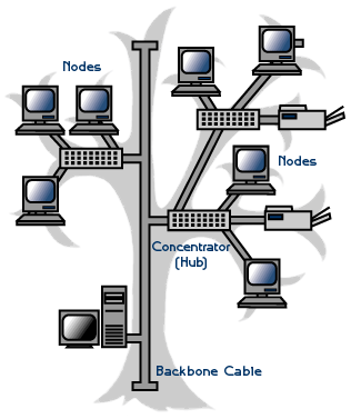
A tree topology combines characteristics of linear bus and star topologies. It consists of groups of star-configured workstations connected to a linear bus backbone cable (See fig. 3). Tree topologies allow for the expansion of an existing network, and enable schools to configure a network to meet their needs.

Fig. 3. Tree topology
Advantages of a Tree Topology
- Point-to-point wiring for individual segments.
- Supported by several hardware and software venders.
Disadvantages of a Tree Topology
- Overall length of each segment is limited by the type of cabling used.
- If the backbone line breaks, the entire segment goes down.
- More difficult to configure and wire than other topologies.
5-4-3 Rule
A consideration in setting up a tree topology using Ethernet protocol is the 5-4-3 rule. One aspect of the Ethernet protocol requires that a signal sent out on the network cable reach every part of the network within a specified length of time. Each concentrator or repeater that a signal goes through adds a small amount of time. This leads to the rule that between any two nodes on the network there can only be a maximum of 5 segments, connected through 4 repeaters/concentrators. In addition, only 3 of the segments may be populated (trunk) segments if they are made of coaxial cable. A populated segment is one that has one or more nodes attached to it . In Figure 4, the 5-4-3 rule is adhered to. The furthest two nodes on the network have 4 segments and 3 repeaters/concentrators between them.
NOTE: This rule does not apply to other network protocols or Ethernet networks where all fiber optic cabling or a combination of a fiber backbone with UTP cabling is used. If there is a combination of fiber optic backbone and UTP cabling, the rule would translate to a 7-6-5 rule.The speed of networking switches is vastly improved over older technologies, and while every effort should be made to limit network segment traversal, efficient switching can allow much larger numbers of segments to be traversed with little or no impact to the network.
Considerations When Choosing a Topology
- Money. A linear bus network may be the least expensive way to install a network; you do not have to purchase concentrators.
- Length of cable needed. The linear bus network uses shorter lengths of cable.
- Future growth. With a star topology, expanding a network is easily done by adding another concentrator.
- Cable type. The most common cable in schools is unshielded twisted pair, which is most often used with star topologies.
Summary Chart
| Physical Topology | Common Cable | Common Protocol |
|---|---|---|
| Linear Bus |
Twisted Pair Coaxial Fiber |
Ethernet |
| Star |
Twisted Pair Fiber |
Ethernet |
| Tree |
Twisted Pair Coaxial Fiber |
Ethernet |